| <<< Multimeter ET828 from Vevor | Ultrasonic cleaner ZX-080S >>> |
Arduino LED Shield from NextPCB
The gadget in moving pictures with audio
The PCB shown in the video was provided to me by NextPCB. You can commission your own circuit board on their website. The following advertising text was written by NextPCB; NextPCB is responsible for the accuracy of the information:
************************************
Sponsored By HQ NextPCB.
Order high-quality, reliable PCB starting at $1.9, multilayer starting at $6.9:
https://www.nextpcb.com/pcb-quote
Enjoy free PCB assembly for 5 boards:
https://www.nextpcb.com/blog/Free-PCB-Assembly
Order electronics components for $50 and enjoy free international shipping:
https://www.hqonline.com/
HQDFM free online PCB Gerber viewer:
https://www.nextpcb.com/free-online-gerber-viewer.html
************************************
By purchasing via the specified affiliate links, you support HOITG without any additional costs for you - thanks!
The shield was created for my second project HomoFaciens.
How Open Is This Gadget?
The design data required to manufacture a circuit board can be created with open source software. I used KiCAD for this project.The design files of this Arduino LED shield are available as Download-Package.
Über die Platine
Figure 1: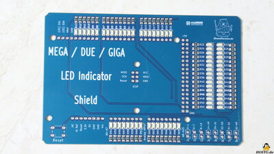
In collaboration with my sponsor NextPCB I have developed a shield for the Arduino MEGA, DUE or GIGA. The purpose of the board is to display the switching states of the input and output pins. For the first time, I made use of the NextPCB assembly service with this board so that I didn't have to solder the SMD components myself. In the the video of this chapter I show you how the assembly service works and what needs to be taken into account.
I created the design of the circuit board using the KiCAD software in version 7. NextPCB is a sponsor of this open source project to create professional layouts of electronic circuit boards, and so helps that this software can be continually developed further. The documentation for KiCAD is also at a high level and together with the large community, this program is a good choice to enter the world of printed circuit boards.
In terms of circuitry, my project is anything but complex; it only involves 70 LEDs, each of which is connected via a 1 kiloohm series resistor between the 70 GPIOs and ground. The LEDs can be deactivated in groups via 8 jumpers.
After the layout has been completed, the files required for production must be exported from KiCAD, which can be done quite quickly using the "Fabrication Outputs" menu item. Don't forget to run the "Design Rule Checker" to see whether all components are connected properly.
Manual rework is only required for the list with the Bills Of Materials, which is essential for the assembly serice. This is a table in CSV format that must be edited using an appropriate program such as LibreOffice. NextPCB offers a template on its website that must be filled with the list of your components. A "DNP" for "Do Not Populate" can also be entered to indicate that these parts should not be placed on the board by NextPCB. Here, this is the case for the through hole components. The files generated in this way are required for the order.
The ordering process on the NextPCB website is not rocket science and if something remains unclear, you can ask questions directly on the site.
Technical data
| Category | Value | Remark |
|---|---|---|
| Dimensions |
119.4x78.9mm |
|
| Layers | 2-Layers |
Unboxing
Figure 2: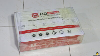
The boards arrive well packaged after a few days via express shipping.
Assembling the through hole components
Figure 3: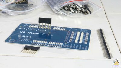
What is still missing are the components for through-hole mounting:
Additional pin headers that are plugged onto the pins help to align the pin headers correctly when soldering. Thanks to the soldering mask, the components are soldered very quickly, even with the many pins being close together. With the clear labeling, errors in this final production step are virtually impossible.
The finished shield
Figure 4: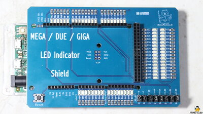
Whether everything works as intended can be seen after plugging the shield onto an Arduino DUE board and writing a few lines of code. For the assembly I chose green LEDs and indeed, all pins are connected correctly. The SMD LEDs shine brightly even with just 3.3V from the Arduino DUE. I would like to use the board to illustrate some basics of microcontroller programming.
My conclusion
Ordering an assembled board requires additional steps when preparing and exporting the files, but it is not rocket science. The SMD components soldered by NextPCB are neatly attached to the board and production proceeds quickly.| <<< Multimeter ET828 from Vevor | Ultrasonic cleaner ZX-080S >>> |
![]()
![]()
![]()