| <<< Test procedures laser cutters | FlyingBear LaserMan >>> |
D1 Pro from xTool
The gadget in moving pictures with sound
Buy the xTool D1 Pro via one of my affilate partners:
xTool shop USA
xTool shop UK
xTool shop France
By purchasing via the specified affiliate links, you support HOITG without any additional costs for you - thanks!
How Open Is This Gadget?
| Category | Remark | Info |
|---|---|---|
| Firmware |
Firmware is closed sorce, not grbl compatible. |
? |
| Software |
Machine data can be processed only via SD card with open source toolchains. The PC software to control the machine is closed source, there is no version for Linux available. |
? |
| Hardware |
The components are very easy to replace, common screw types, nothing is glued. |
? |
| Elektronik |
Mainboard uses a common ESP32 microcontroller. |
? |
| Website |
The website offers firmware updates for download. |
? |
About the gadget
Figure 1: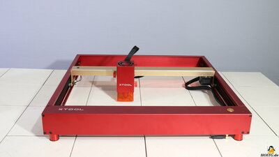
The D1 Pro from xTool is a laser engraver and cutter with a very robust design, a working area of 43x39cm and a 20W diode laser.
Technical Specs
| Category | Value | Remark |
|---|---|---|
| Work area | 430x390mm | |
| Dimensions | 60x59x16cm | |
| Laser module |
Laser power: 20W Input power: 72W Focal length: ??mm Wavelength: 445nm |
Type MD1 Pro-L20 |
| End schwitches | X, Y at both ends | |
| Energy consumption | Power supply: 25V at up to 6A |
Package contents
Figure 2:
Included in the package are a power supply that delivers 25V output voltage at up to 6A, a micro SD card and a USB cable for data transfer from a PC, tools for assembly, and some materials that can be processed with the device. A "lathe" with which round objects can be engraved is available as an extra.
Also included are safety goggles, which must be worn when handling the device!
Assembly
Figure 3: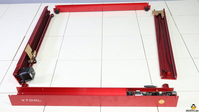
Only 16 screws need to be tightened to assemble the frame and the cables have to be plugged in and secured with zip ties - everything is done very quickly and you really can't do anything wrong.
Mechanics
Figure 4: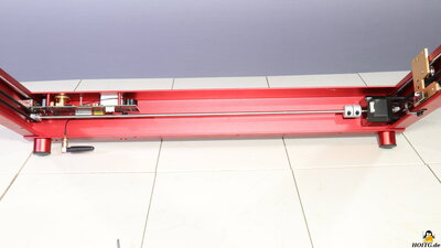
The axes are guided by ball-bearing steel rollers along round steel rods. The mechanism on the two sides of the Y-axis shows no noticeable backlash, nothing wobbles or bends here.
The guide along the X-axis, to which the laser head is attached, has a spring-loaded suspension of the lower, third steel roller. This means that the laser head can be moved relatively easily by hand, but during operation the spring tension is sufficient to hold the laser in place.
Both sides of the Y-axis are driven by just one stepper motor - the pulley on the second side is connected to the motor shaft by a round rod. With this system, the axes remain at right angles, even when the machine is switched off.
The timing belts are tensioned very conveniently at the ends with the deflection rollers. Just one screw needs to be loosened, the desired tension has to be set with a second screw and finally the first screw has to be retightened - this system is used for all three timing belts.
Electronics
Figure 5: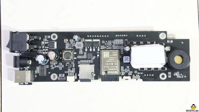
There are limit switches at both ends of both axes - a total of 4 optical switches prevents the laser head from being moved to positions outside the maximum working range.
The mainboard is placed well protected at the front of the frame.
The on-off switch, as well as the sockets for the power supply and the USB interface are soldered directly onto the circuit board.
A push button is actuated via a brass button at the top of the frame - this allows the machine to be stopped quickly should something go wrong with a job.
A fairly loud piezo buzzer is used to output acoustic signals.
The two drivers for the stepper motors are located under a rubber block that serves as a stop for the circuit board on the frame.
Gcode files can be processed directly by the machine via a micro SD card reader.
An ESP32 with integrated WLAN is used as microcontroller.
Laser module
Figure 6: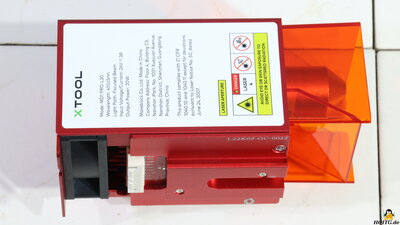
The laser module with the label MD1 Pro-L20 has a maximum output power of 20W at a wavelength of 445nm. With a voltage of 24V at up to 3A, this corresponds to an electrical input power of 72W.
The laser module is prepared for Air-Assist.
A second laser diode, emitting a low-power red light beam, projects a crosshair onto the workpiece, making it very easy to position the laser head.
The laser module is focused by adjusting the height above the workpiece so that the fold-out tool touches the surface. If thicker material is to be cut, the focus point can be placed under the material surface - the tool can be adjusted accordingly via a printed scale.
Extras
Figure 7: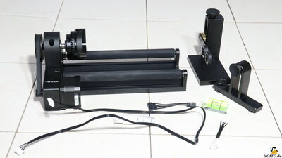
The lathe is driven by a separate stepper motor. This stepper motor is connected to the main circuit board instead of the Y-axis motor, which must be done while the machine is switched off, otherwise the stepper motor driver could be damaged.
The lathe comes with many adapters so that nearly any cylindrical surface can be engraved.
Tests
Figure 8: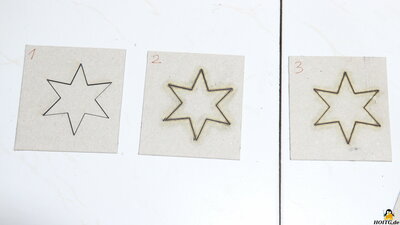
The cutting performance is tested on a stack of 2mm cardboard.
2 layers of cardboard are cut through in one pass at a cutting speed of 240mm per minute.
Details on the test procedure.
Figure 9:
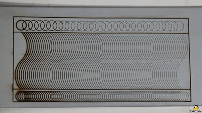
Engraving is tested on stainless steel. You can see how finely engraved and what depth can be achieved.
The speed is gradually increased from left to right.
Details on the test procedure.
Figure 10:
More examples done with the LaserMan
My conclusion
Mechanics and electronics of the D1 Pro did not show any weaknesses in operation. Unfortunately, the firmware is closed source, which also applies to the associated PC software, for which there is also no Linux version available. The only option left is to transfer data via a micro SD card. The file to be processed must be saved on the SD card under the name "tmp.gcode", then pressing the "Start" button is sufficient. to process the file.| <<< Test procedures laser cutters | FlyingBear LaserMan >>> |
![]()
![]()
![]()